
MetroM: Circuit Board Transit Diagrams by Lifeclocc
Currently Funding on Kickstarter
It all started while I was building Lifeclocc. I’ve loved trains since I was a kid and I used to take the trains for the entire length of the line when a new one opened. While I was laying down the copper tracks (yes I know it’s actually called traces) for my Lifeclocc, I was thinking how similar they look to train lines. It was about this time that I saw LTA had released their plan for the 2030 MRT system and got the idea of putting the system design onto a PCB, because why not? Ever since I had figured out that PCBs were such a simple thing to manufacture, I had been on the lookout for anything I could conceivably build using a PCB.
This post is split into 4 main sections:
- Creating the Designs
- Creating the Lighting Circuit
- Colouring the Lights
- Using Transistors to Control the Lights
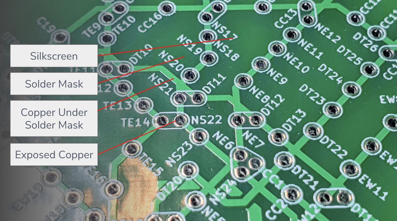
A quick primer on PCB art:
There are 4 layers on a PCB
- Substrate (FR4) - Gives the PCB the rigidity. Can also be other materials.
- Copper - Conducts the electricity
- Solder Mask - Protects the copper and prevents solder from shorting the circuits
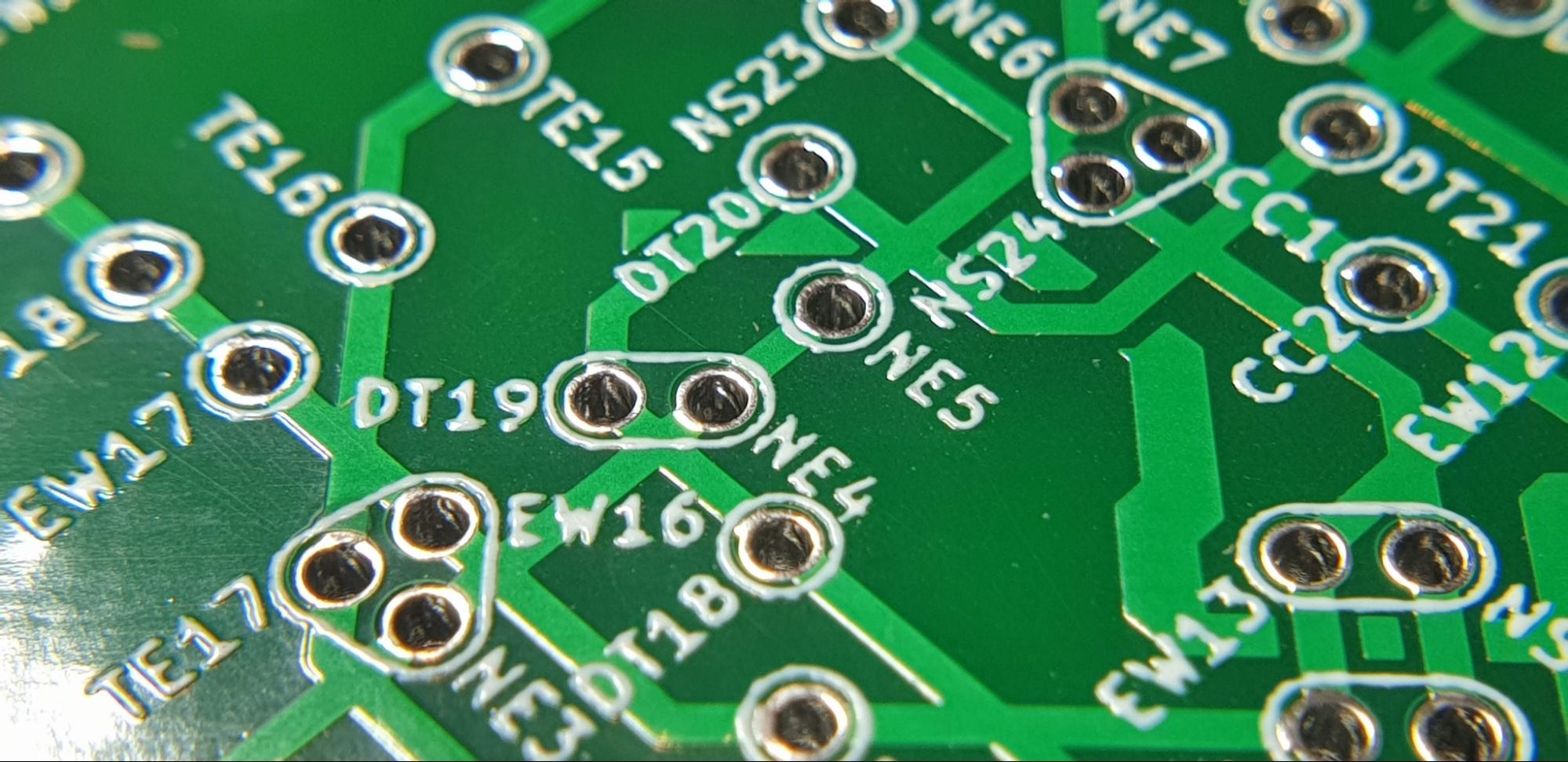
- Silkscreen - Purely decorative, usually used for text and other markings
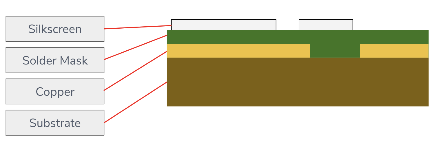
These layers all serve a specific purpose in the structure of the PCB, but by adding removing combinations of the layers you can get different colours, from that you can make basically any image with about a palette of 3-4 colours.
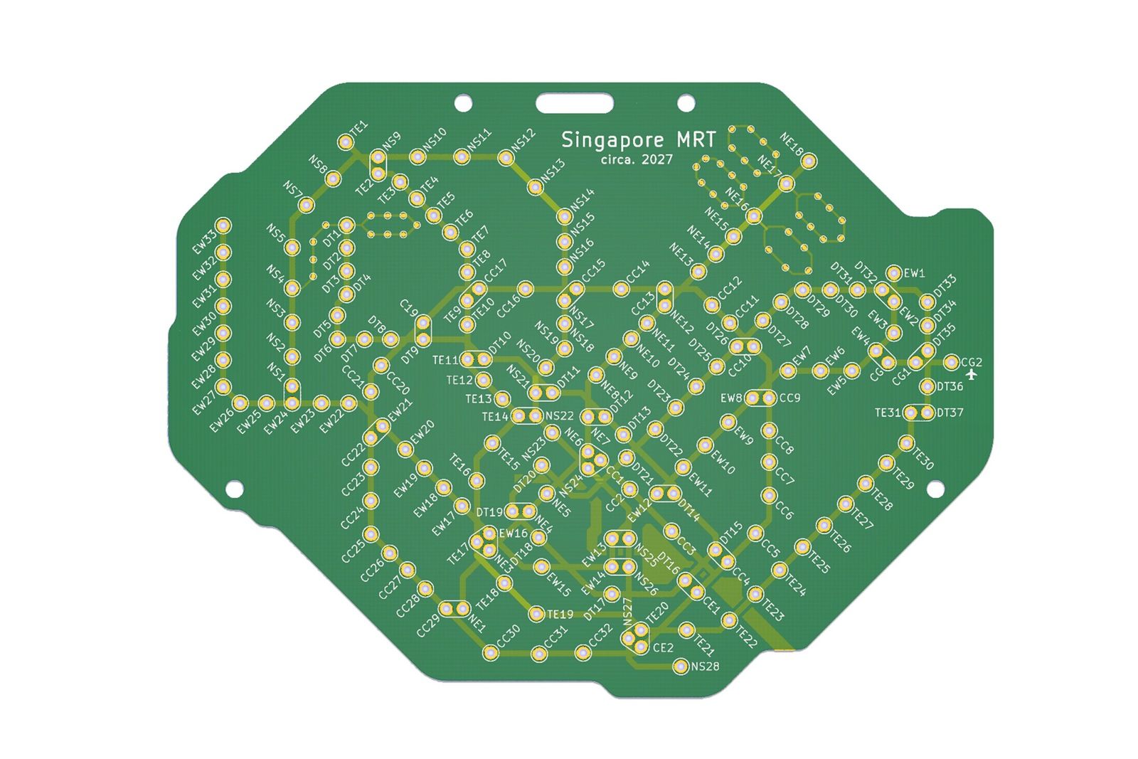
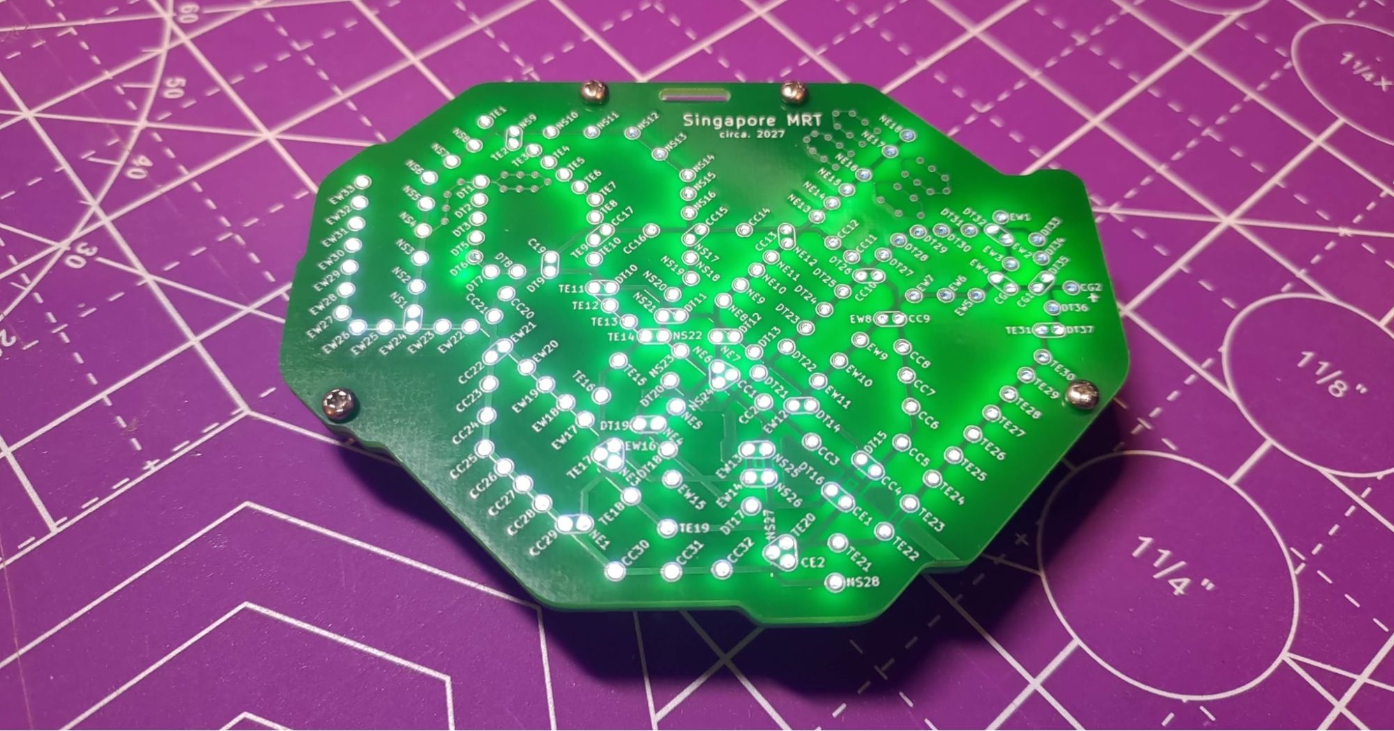
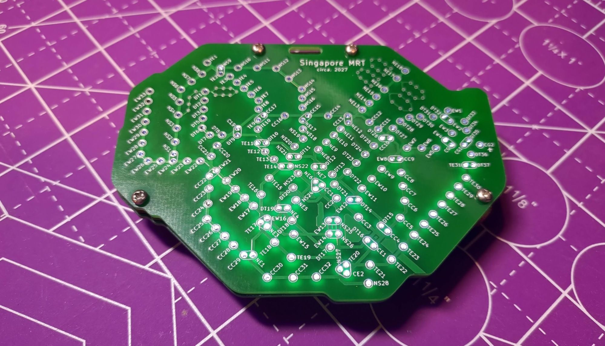
For example, let’s take a look at my completed Singapore map:
Creating the Designs
The initial idea was pretty straightforward. I wanted to have a purely aesthetic PCB where the stations were through-hole mounting points and the train tracks were copper traces. I could use the silkscreen layer to label the stations. The process was also simple, albeit tedious. I had created PCBs before, and I had attended a talk specifically on how to make PCB art, so it wasn’t anything new to me.
Singapore
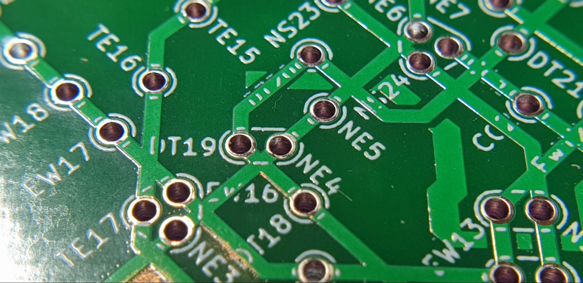
The design process is not much different from designing any map in illustrator or photoshop. All I had to do was to create a custom footprint in KiCad, position the stations roughly according to the official LTA map, and then connect them with copper traces. I chose to use 0.7mm thick traces just so that they would be more visible, and the initial renders looked great.
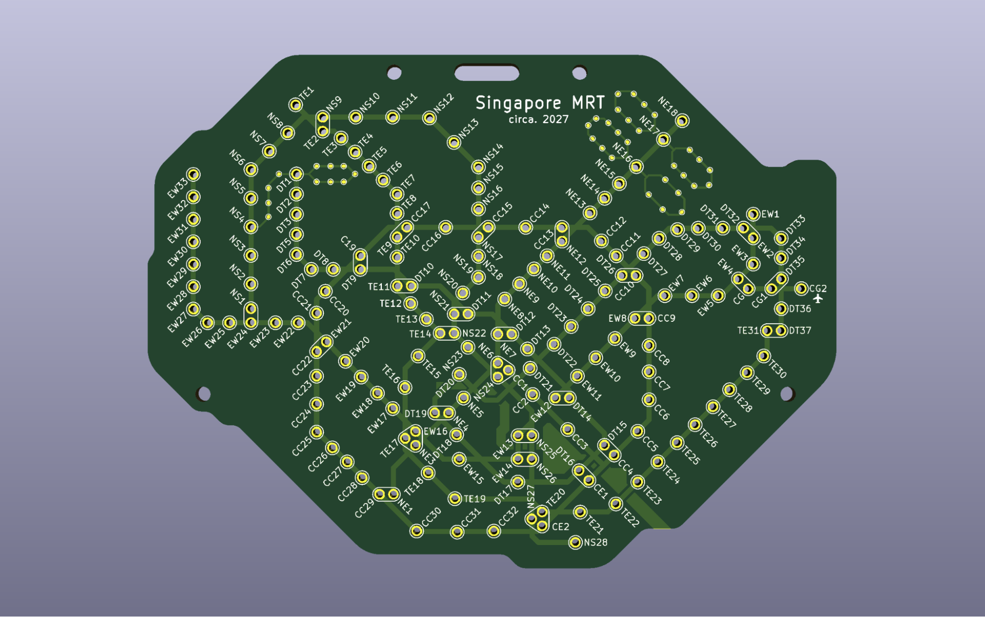
I ordered the design from JLCPCB, a company that I’ve used before and quite like. I generally haven’t had many issues with them, but this project was surprisingly full of quality issues.
On the first batch, the silkscreen was pretty badly printed. This hadn’t happened before, so I am unsure what the cause was.
I could have tried another manufacturer, but I really did not want to test out multiple manufacturers. One thing I did notice was that the silkscreen that printed where there was copper underneath would come out well. So to solve it, I just duplicated the whole silkscreen layer and gave it all a copper backing. This “fix” provided consistently well-printed silkscreen layers.
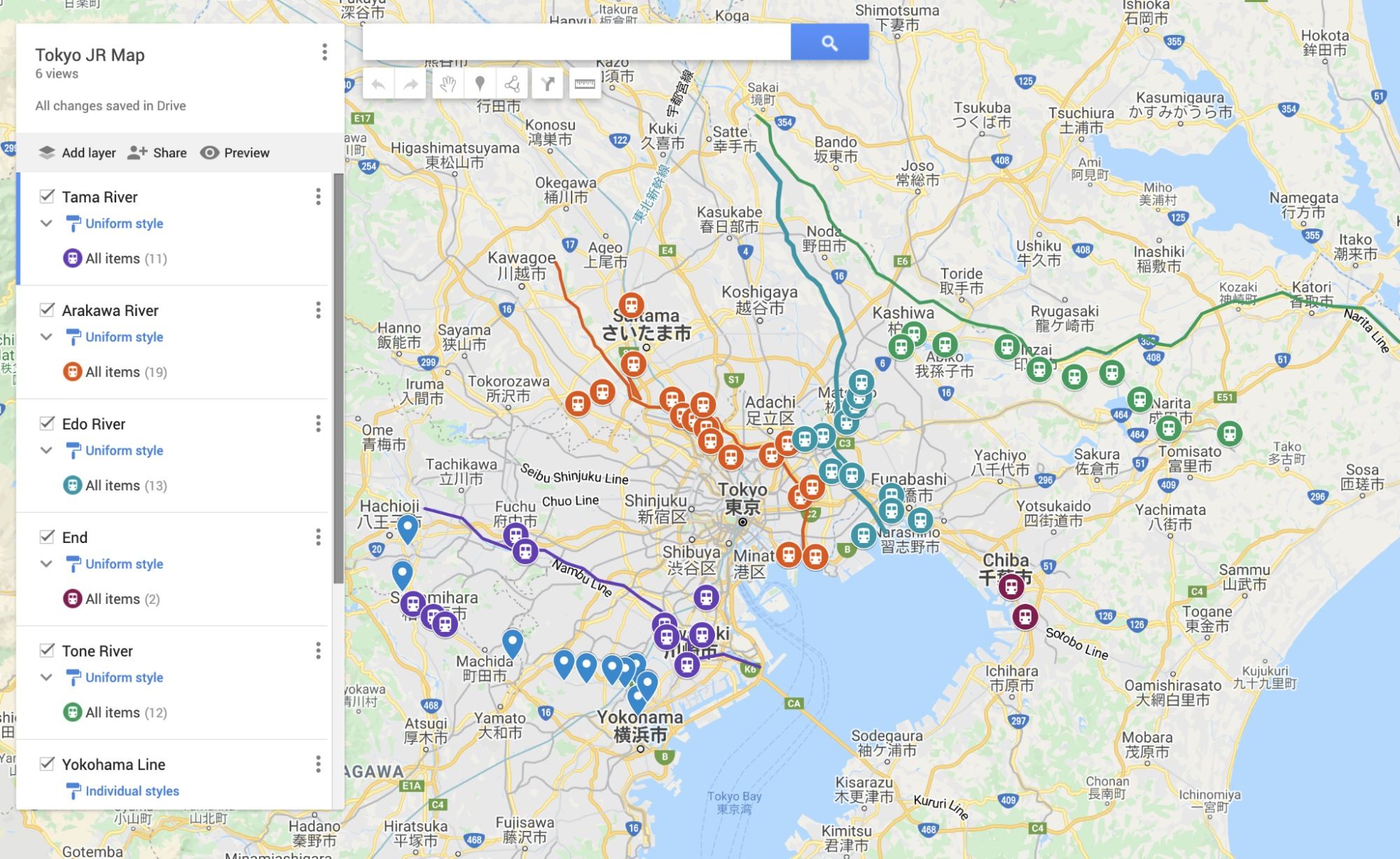
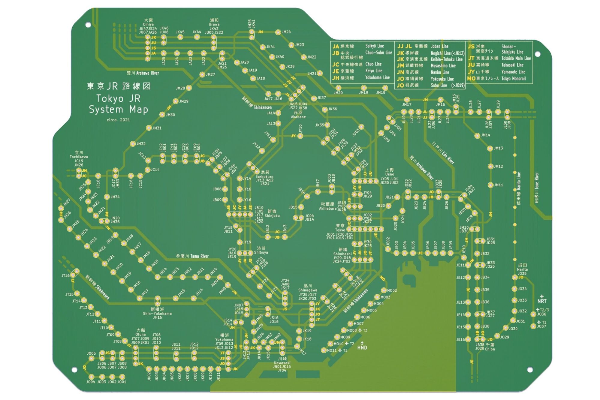
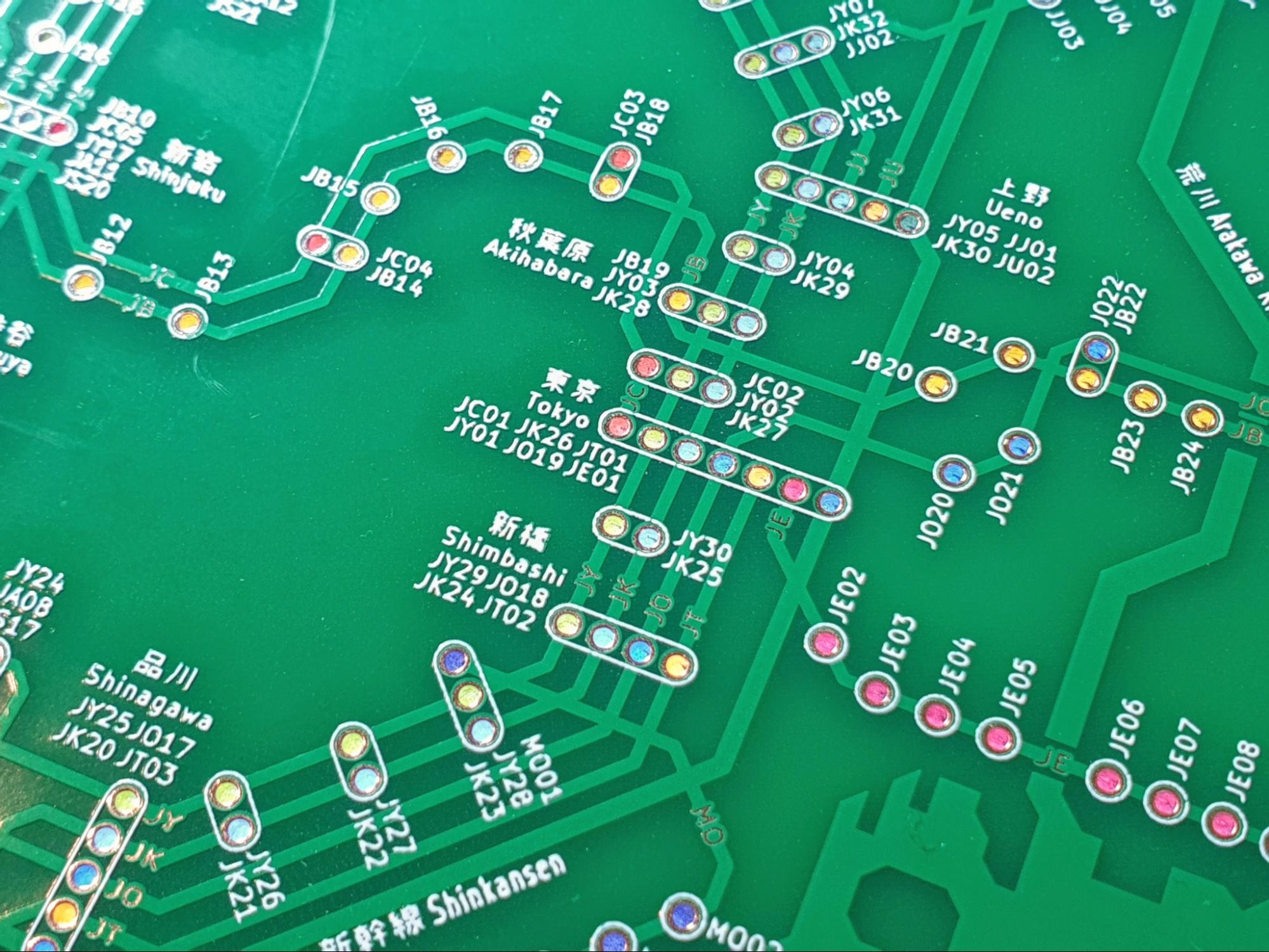
Tokyo
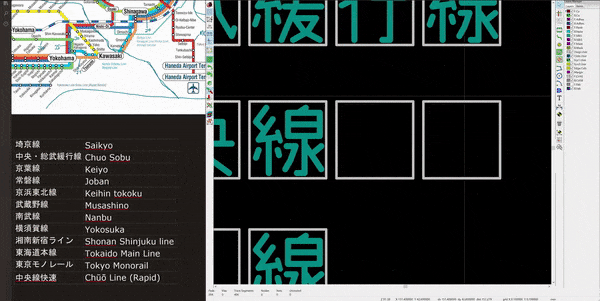
The next board I built was the Tokyo one. One thing KiCad does not do is support unicode text, so I could not just type Japanese. There are a few ways of solving this problem, and somehow I chose the most tedious one.
- Write the Japanese in another software and import it as vector images.
- Download a development build of KiCad that supports different fonts.
- Draw every single word with lines (I chose this)
To be fair, I did like the idea of having a very PCB-ish font for the Japanese, so I drew it myself. But this took way more hours than necessary. Here’s a timelapse of part of the long painful process of checking all the stations and drawing the kanji. And a longer video as well if you're into it.
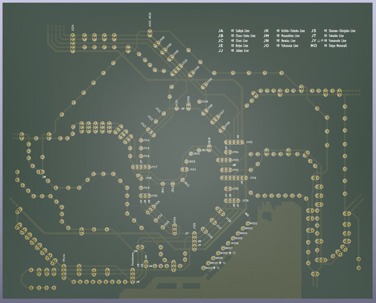
The board looked pretty cool, but still felt somewhat empty. That’s when I decided to draw in the main rivers as well, which felt apt. Cue another few hours of staring at google maps to ensure I get the station relative positions accurate.
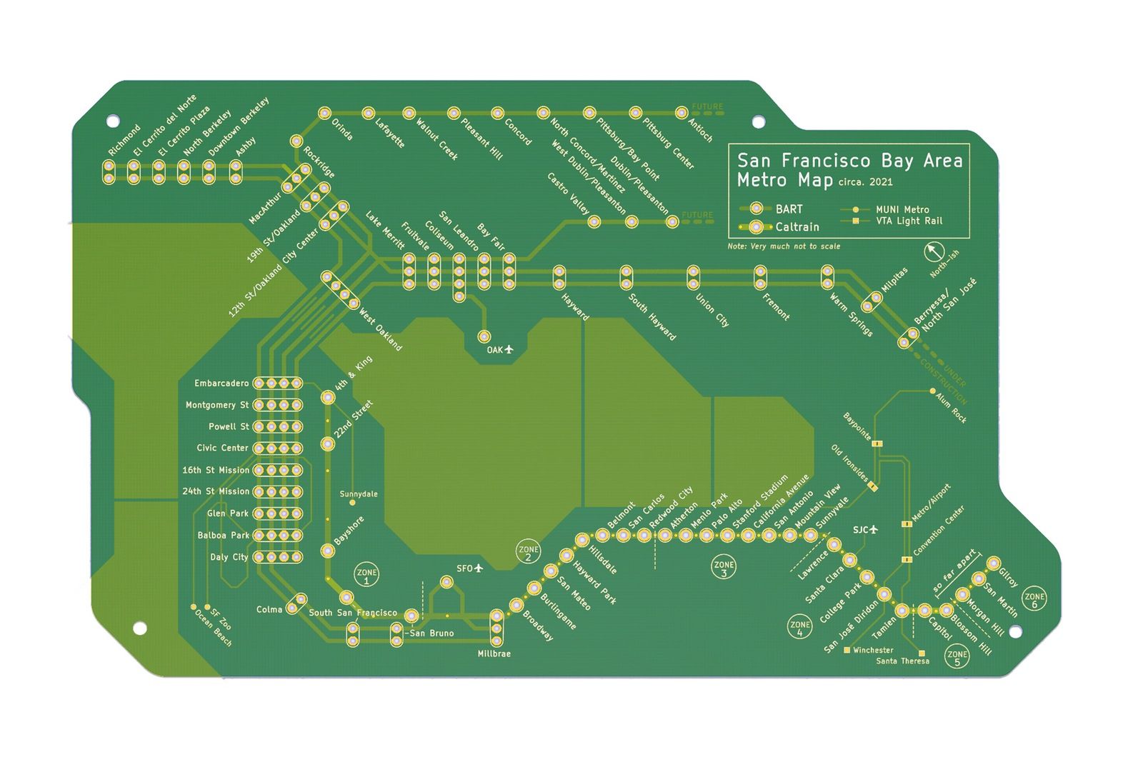
Bay Area
The Bay Area Map was actually the simplest one to do since the train system is so sparse. I honestly am not terribly excited about the train system here, but since I do live in the Bay Area, I felt like I should do it for completion’s sake.
It took me about 3 hours to complete.
This was my first expected stopping point. I had a bunch of cool PCBs to show off and I guess it was time to work on other things. But as you can see by the scrollbar on your right, we’re far from the end.
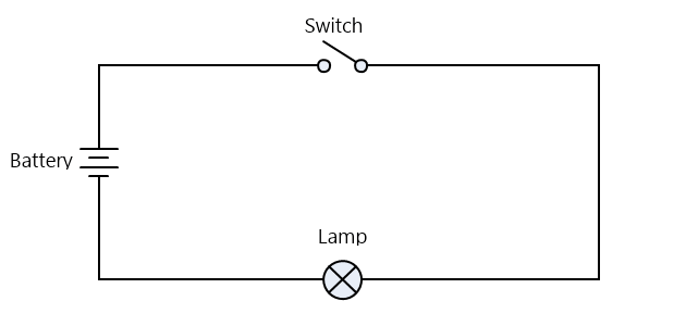
But does it light up?
That's the question I got from every single person I showed this to. Honestly, the more I looked at it, the more it made sense to expect it to light up. It’s a circuit board, that almost seems like the least it should be able to do.
How hard can putting a few LEDs on a board be?
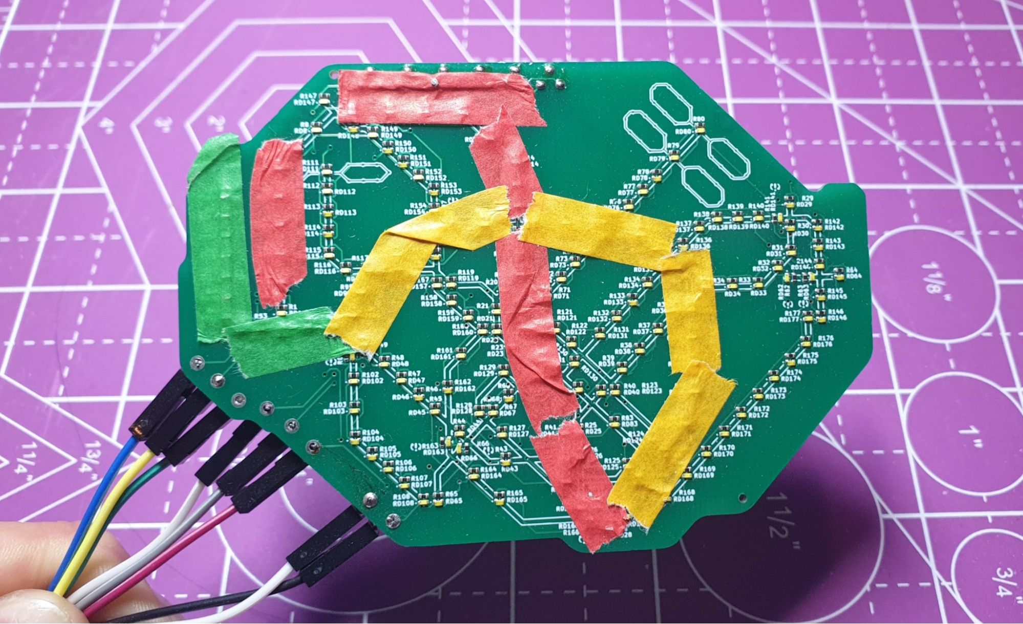
Idea 1: Put the LEDs on the bottom side.
Maybe if the LEDs were behind, the light would shine through the holes or shine through the board and light it up. The front panel was already being used for the design so I couldn’t really use it for wiring. I was also pretty sure that the lighting would not be doable on a single layer.
Either way, I manufactured a lighting test board to see how good the LED would look from the front if stuck on the back of the board.
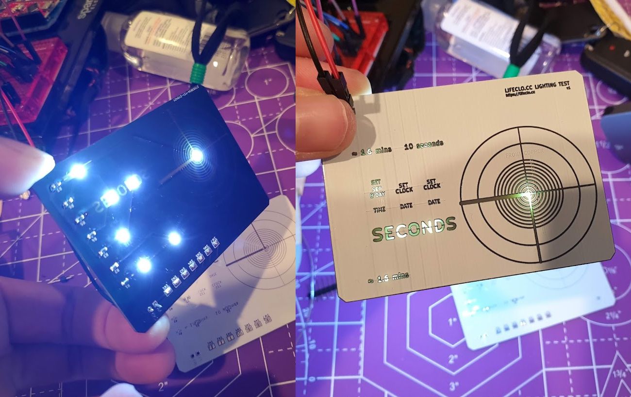
It kinda worked, but that definitely wasn’t the look I was going for.
Idea 2: 4 layer PCB
If I can’t do the wiring on a single layer, I could probably do it on a 4 layer PCB. The issue is I had never worked with a 4 layer PCB before and it also becomes way harder to debug. We still ended up with the issue of the LEDs being on the back of the board.
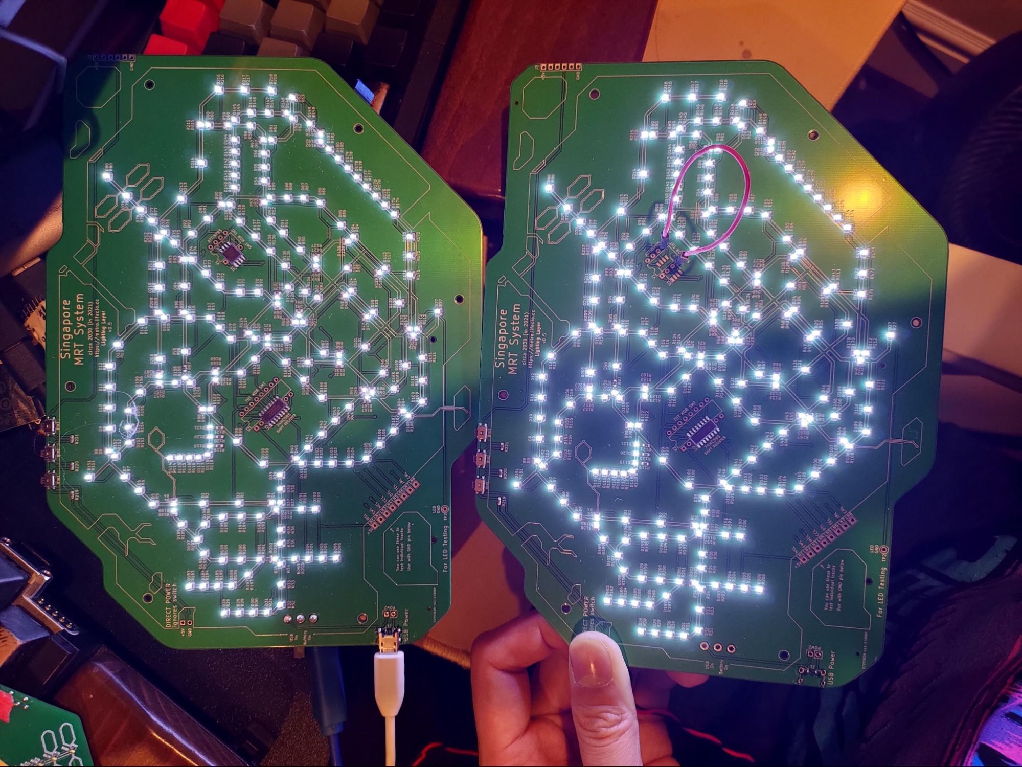
Idea 3: 2 PCBs?
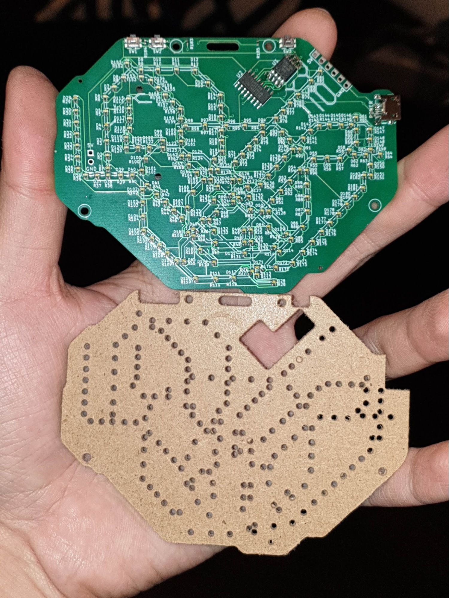
That’s when I had the idea of creating a completely separate PCB to deal with the lights. It was effectively the same as a 4 layer PCB electronically speaking. Using the same concepts as a sandwich case when making keyboards, I would simply screw 2 PCBs together, with the one behind containing the lights. The lighting layer could look as ugly as I needed and it wouldn’t matter since it’s all going to be hidden anyway.
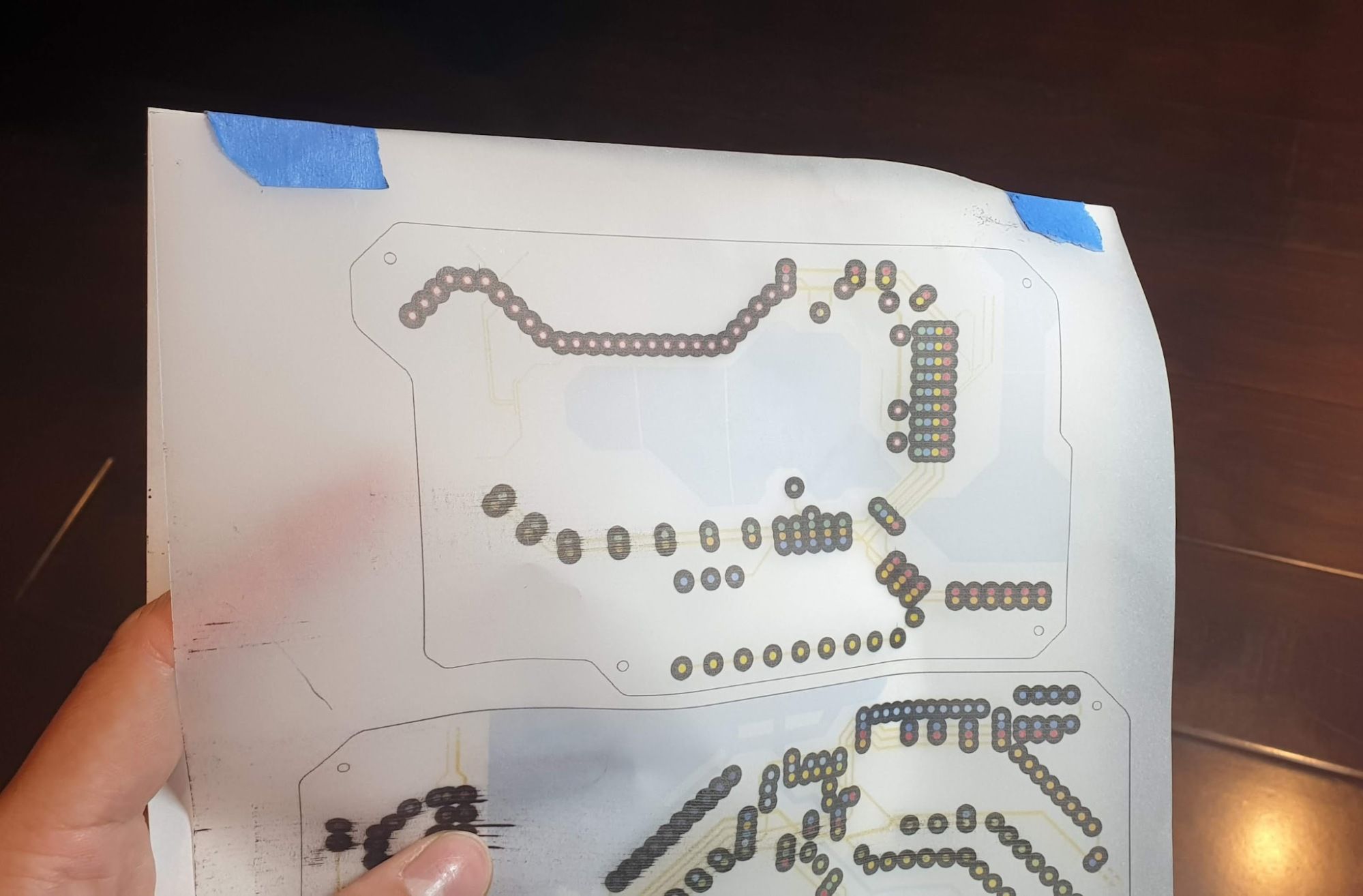
All I had to do was to (1) position every LED onto the same positions as the holes and then (2) give each LED an accompanying resistor, then (3) draw the traces.
Positioning the LEDs might have been possible with a script, but it felt easier to ensure the correct LEDs were going to the correct places.
I still managed to automate steps 2 and 3, saving me a lot of time.
Manually aligning every single resistor was a huge pain. After some research into custom Kicad plugins, I realised that the entire Kicad file is completely text-based. I then wrote a script that would place a resistor 1mm below the corresponding LED based on the designation. I’ll write another post detailing how I did that sometime in the future.
Automating the routing was a matter of using a software like freerouting to draw the traces for me. Though there are purists appalled by the idea of an automated router, it did save me many hours for effectively the same result.
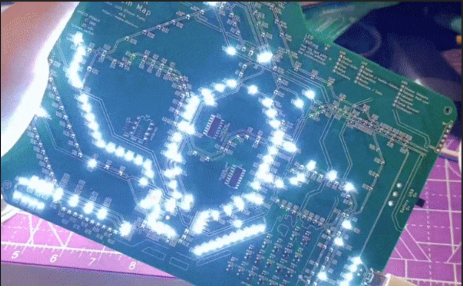
With all that out of the way, I finally managed to get a prototype and I tested it. And the result was pretty disappointing.
How do I fix light bleed?
This was already quite cool as it is, but the light was leaking all over and even shining through the board itself.
My first instinct was to create something to guide the light. So I bought some 3mm thick MDF boards with the intention of laser cutting the holes to match up with the PCB holes. That turned out to be a great solution, except that my Snapmaker laser was too weak to cut anything except thin cardboard.
Sidetrack, this is the umpteenth time the Snapmaker has disappointed me. I ended up buying a dedicated laser cutter to deal with the production of this item, but that’s a story for another post.
“Luckily” I still had the CNC machine part of my Snapmaker which I could use to CNC the insert I wanted. This proved to be way harder than I bargained for due to uneven surfaces and drill bits snapping. I spent an entire day just figuring out how to level my CNC bed, which I documented here.
Finally, after a lot of tinkering, I had my insert, and it worked wonders. It even had the added benefit of preventing the electronics from being squished between the two layers of the PCB.
It was only later on when I realised that another solution to prevent light bleed was to ensure the whole back of the display PCB is copper filled. But the MDF insert worked very well to protect the electronics so I still kept it.
Controlling the lights
This part was more within the realm of what I was familiar with. I chose to use an ATTINY85 microcontroller and shift register to control the lines individually. I’ve been wanting to use an ATTINY85 for my projects for a while. It’s a small microcontroller with 4 pins and can be used for very simple Arduino projects.
Programming an ATTINY is supposedly doable with Arduino code, and all you needed was another Arduino Uno to act as the programmer bridge. I spent a long time trying to figure out how to get this working to no avail. In the end, I bought the SparkFun ATTINY85 programmer which worked wonders for me.
The next problem I encountered was that the ATTINY was seemingly running out of memory really quickly. That didn’t really make sense because I only had a few patterns saved and a few booleans shouldn’t take up the 2kB of memory that quickly.
Here’s a quick low-level programming lesson:
If you declare something like bool a; it does not take up 1 bit, even though a bool should only take up 1 bit. This is because of the word size on the hardware level, and the smallest addressable memory space is usually 1 or 2 bytes, depending on the processor. This meant that when I declared an array of bool a [8]; it was taking up 8 bytes instead of the 1 bit I expected it to take.
One code optimisation later, and I had a working board that was completely self-contained with the ATTINY and shift register being soldered directly onto the board and looking super cute.
This was again where I intended on stopping. But something was missing.
White lights are cool, but coloured lights are cooler
Showing the product to my friends again, the next logical step was, why are the lines all white? Every metro map has coloured lines. In fact, the colours are one of the most distinctive features of the metro maps.
If I used coloured LEDs, I would be limited to only about 5 different colours. I could use RGB LEDs but then the electronics would get 3x more complicated and my Singapore board was at the limit of how much complexity I could reasonably fit onto a 10cm board.
Idea 1: Washi tape
If I used translucent coloured tape, I could probably colour the lights if I stuck it on top of the lights right?
This worked to a limited extent, but was very time consuming and was pretty hard to pull off unless I did some paper crafts with an exacto knife. If I wanted to mass-produce this product, this would not be feasible. Also the colour was barely visible.
Idea 2: Printing on paper
If washi tape is just coloured paper, why not just print the design onto actual paper from a printer? A single sheet didn’t do much, but I found that if I stacked 2 or 3 sheets, the colours got a lot more saturated and started to look pretty great.
In fact here’s my Instagram post excitedly showing off the results:
The problem with this is that the lights became much dimmer. Of course, that would be the case, since I was putting it through 3 sheets of paper.
Idea 3: What is more transparent than paper? Tracing paper!
I didn’t even know you could print on tracing paper, but I found some printable tracing paper and went with that. My printer actually threw a fit trying to print on tracing paper, it kept sucking my paper in, crushing it and telling me there was no paper.
I was going to rage quit when I had the idea to stick a piece of regular paper to the tracing paper. And wouldn’t you know it, it worked wonders. My printer accepted the tracing paper and printed on it without any issue.
Idea 4: Printing on transparency paper
I still felt the tracing paper was blocking quite a bit of light, and that’s when I realised that there are printable sheets of transparent “paper” (ok, more of plastic?) that you can print on for the specific purpose of projecting with an OHP (remember those?)
The transparency paper printed without any problems, and came out beautifully. Surprising, since I expected the printer to reject the paper.
Though, when I used it as a filter, I did find the light too piercing. In the end, I decided to put 1 sheet of tracing paper to diffuse the light, and 2 sheets of transparency paper to saturate the colour.
Lights were still too dim
Honestly, it was barely visible in brighter light. It looked fine under my dim room lighting but I felt like the LEDs could get brighter. In fact, I was pretty sure most other LEDs I’ve seen were much brighter than what I was seeing. Changing the resistance of the resistors also seemingly did nothing to solve that issue.
The issue turns out to be that the shift register could only output 20mA of power. I am terrible at reading datasheets, but I’m sure the power consumption of 40 LEDs would be more than 20mA.
I ended up inadvertently solving this issue in the next step. After adding transistors, the lights became as bright as I expected them to be.
I wanted to buy a light-o-meter to figure out exactly how much brighter it became, but it felt pretty unnecessary.
Tokyo Lighting was a pain
At this point, I had working lighting prototypes of the Singapore 2027 map and Bay Area maps. Extending it to Tokyo didn’t seem like there would be any issue, especially since it was the exact same circuit, only that there were 350 lights instead of the 200 that Singapore had.
I was so wrong.
I went through 3 non-working prototypes before finally getting one that would work.
I used the same code and layout as I did for the bay area one, which had 2 shift registers as well. But when it finally arrived, the lights would randomly flicker and spaz out.
Maybe it’s drawing too much power somehow. I guess the shift registers can’t power the 350+ LEDs and there was some electrical interference. No matter, I hear transistors are all the rage these days.
It took about 1 week to figure out what a transistor is and test it on a breadboard to make sure I knew what I was doing. For the uninitiated, a transistor is a switch controlled by an electrical signal. There are 3 pins. If there is no electrical signal on the gate pin, it would prevent current from passing through the other 2 pins. I could use this to my advantage to control the lines without worrying about the shift registers needing to support the current load of all the LEDs.
I chose to use a metal–oxide–semiconductor field-effect transistor (MOSFET) mainly because I have heard of it being used in my keyboards. Once I was confident that I knew how a MOSFET worked, I redesigned the schematic to include MOSFETs this time, and sent another production run.
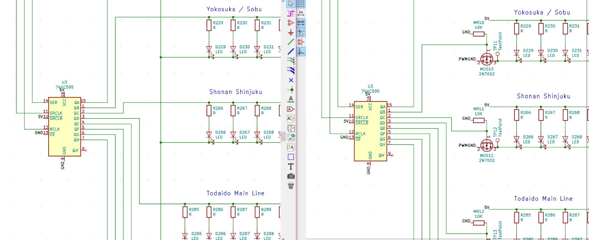
Much to my dismay, it still suffered from the same issues. I was able to light up the lines individually and manually control it, but once I tried to use the ATTINY to control the lights, everything went nuts.
The strange thing was that when I wired the board up to my Arduino Uno, the lights worked perfectly. So I knew it had something to do with the ATTINY. Since I am not an electrical engineer, I honestly had no idea how to even start debugging this issue.
Now I really wanted to use an ATTINY mainly because I thought it looked really cute. I could have upgraded to an ATMEGA328 but then I’d have to figure out how to flash a bootloader and program it. Or, I could just use any readily available Arduino platform, similar to what I did for Lifeclocc.
A quick google later, and the smallest one that was easily obtainable was the Arduino Pro Mini. This did not have a USB port on it and would need a programmer to load the code in. But the same could be said for my ATTINY as well. So I went to get a couple to test.
It solved all my problems and more. I had this flickering issue coming from the ATTINY when the light was dimmed. It wasn’t that noticeable but cameras would pick it up. I guess the clock speed on the ATTINY was a bit too slow and the PWM caused some flicker when I dimmed the LEDs. With the Arduino Pro Mini, that issue was gone completely. Since the larger boards had enough space for the Pro Mini anyway, I didn’t see any issues in just using that instead. Only the smallest Singapore 2027 one stuck to the ATTINY.
At last, I was finally done with this project and I could work on crowdfunding. Or so I thought...
Special Commission
I had posted the original Singapore 2027 map on Reddit and it kind of blew up. It got to a point where a news site contacted me to write an article about it. It was likely because of that, that someone contacted me to create another Singapore map, but a larger one that could be framed on the wall.
I had wanted to make a Singapore 2030 map anyway, and this was a great opportunity to actually build a product for someone. So I took about 6 more weeks designing and manufacturing the new design. I even framed it and it looked pretty great.
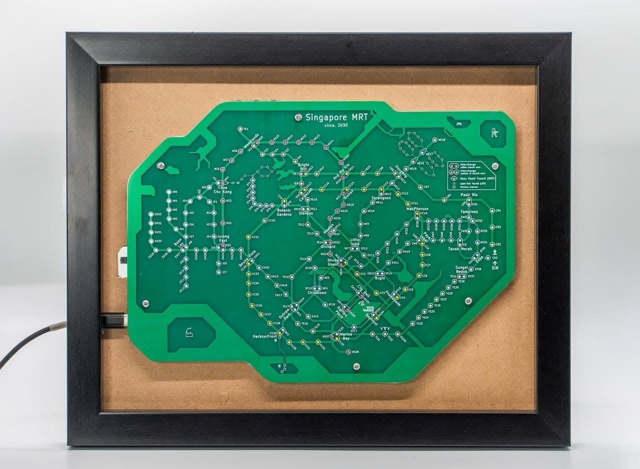
There weren’t many learnings here, except that I messed up some resistor placement (which I could fix by soldering other resistors, and I figured out that using bigger buttons would make the controls easier. Most of what I learnt came from the previous designs.
Ok, I’m seriously done for real this time. No more scope creep. At this point, I want to focus on crowdfunding.
Kickstarter
With that, I had solved almost every glaring issue with the project, and I finally felt that it was ready for production. There were still a few more issues I hadn’t solved, but I wanted to see if people wanted this first before I made any more improvements to it.
The next post in this series would be the research and considerations I went through to produce and fulfil a small run of 100 of these for crowdfunding. Assuming the crowdfunding campaign even succeeds. Now I need to figure out how to market this project so that it does.