This might apply to any generic CNC machine, but I’ve only tested it on a snapmaker so far.
Here’s a short review of the Snapmaker. I’ve used two separate Snapmakers (one belonged to my friend) and both of them have had their fair share of issues. The snapmaker was meant to be a simple to use system where everything just works out of the box. At least that’s what I felt I was paying a premium for, but after using it for a few months, they both came with a myriad of issues. Long story short, don’t bother getting a Snapmaker. You would probably be better off getting dedicated machines, or the creality CP-01 which is less than half the price.
But for those who have already gotten this system and need to get their CNC bed flat, this is how I went about doing it.
Solution:
Flatten a piece of MDF first, then drill holes to allow access to the mounting points. Now you have a flat surface that will allow mounting things anywhere on the board. It will require additional parts and it cost me $50, but at least I can use the CNC properly now.

That’s it. If you want a step by step on how I did it and the story behind it, you can read on.
The Story
In both of the devices I tested, the bed was not properly flat. It was off by about 1mm on the Z-axis from one corner to the other, which didn’t seem like that much of a bother at first. But as I continued to use it, I realised that one side would be cut clean through while the other would still not be cut through.


It’s also fairly obvious from the damage done to the wasteboard that it wasn’t flat. So how would we solve this?
I was under the assumption that the CNC would have an auto levelling feature like it says here, but that seems to be a lie.

Bad Solution 1: Cut deeper into the wasteboard
The simple solution to this would be to lower the drill bit and make it cut even deeper into the wasteboard, but I didn’t really want to constantly damage the wasteboard on one side. That would also mean that on one side of the wasteboard, the bit would experience even more stress and might snap. (I’ve snapped 6 bits to date as it is)
Bad Solution 2: Put a sacrificial MDF board under the thing I’m cutting to protect the wasteboard
This works mostly fine if I want to cut through the entire piece, but if I’m engraving something I would end up with one side shallower than the other, or simply not even engraved at all. It still doesn’t solve the problem of inconsistent stress on the drill bit.
Bad Solution 3: Measure the difference and compensate for it when designing the CNC job.
Yeah no. I don’t even want to go there.
Bad Solution 4: Use the laser module
This sounded great at first, if all I want to do is to cut shapes out of some MDF sheets, why not just laser it out? Well, that’s when I discovered that the Snapmaker laser module is super weak and can only cut paper. I do feel slightly cheated thinking it would be able to cut thin pieces of wood at least.
Apparently the “correct” solution?
Flatten the wasteboard with a big router. At least this is what I got from the few posts I had on the snapmaker forum and the “official” answer above.
I didn’t really want to drill into my wasteboard, and the other option of simply flattening a piece of MDF had issues as well. For instance, how do I hold it down, and how do I access the inner mounting points? This is the solution I managed to come up with that has worked for me.
Additional materials needed:
- 1 inch (or any big) drill bit (Usually has a 1/4” shaft compared to the 1/8” that comes default)
- A new collet to fit the new 1/4” drill bit (The snapmaker uses the ER11 collet)
- A big enough MDF board. I bought a 6mm thick one but it seems that I could have made it work with a 3mm thick one.
These set me back about $50 in total from Amazon US. You might be able to get them cheaper elsewhere.
I used Fusion360 to create the jobs. If you don't know how to do that, I'd suggest watching the Snapmaker tutorial on how to use fusion.
The steps are as follows
- Manually cut a piece of MDF to a small enough size to fit within the working area, but with enough excess at the top and bottom to hold down. In my case I made it 18 cm and 28 cm.
- Create a job that will run the drill bit over the entire surface of the work area. I made mine 17 cm by 17.4 cm.
- Run the job a few times, lowering it by 0.2mm each time to ensure nothing breaks.
- Create another job to drill the holes to allow access to the mounting points.
- Cut off the excess parts from the top and bottom, you now have a jig that will make the work surface flat.
Step by Step with Pictures
Step 1: Cut MDF to size
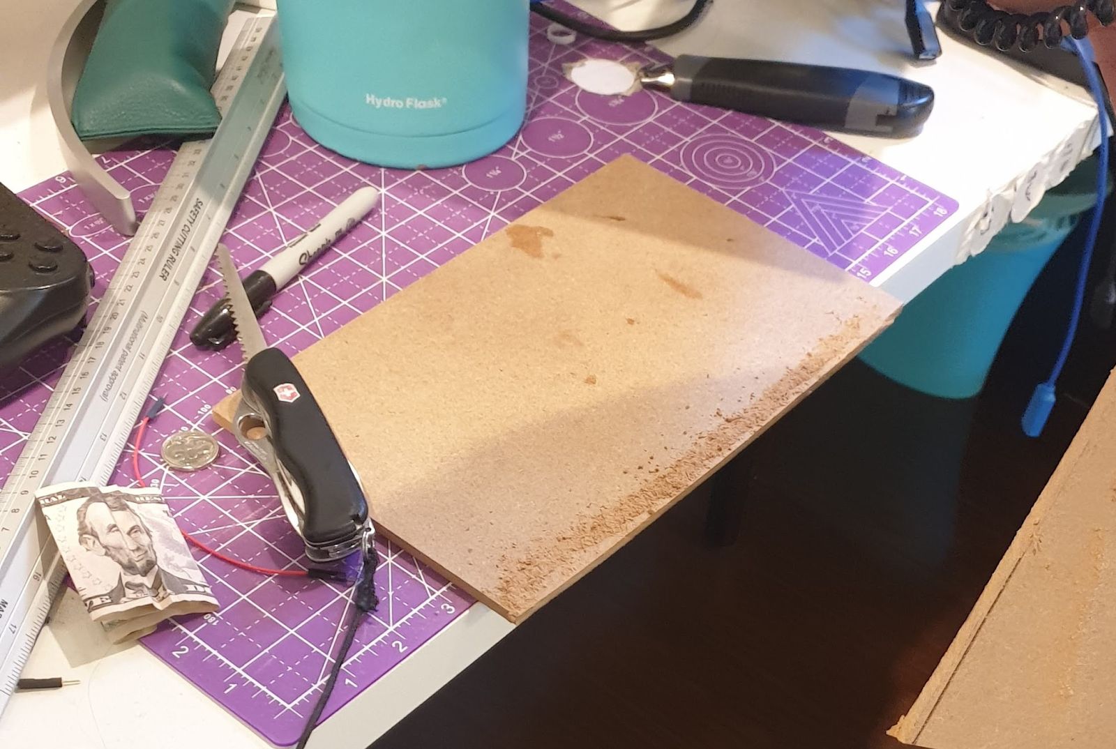
I’m using the A250, which has a wasteboard size of 20cm by 25cm (between the mounting points). Since I needed some way of holding down the piece of MDF, I needed to leave the sides exposed so I could clamp the MDF down. I ended up cutting a piece of MDF to be 18cm by 28cm. Yes this does stick out a bit on the top and bottom, but as you will see later in the pictures, it’s actually fine and even gives me a bit more space on the top and bottom to work with.

Step 2: Create a Job that will flatten the MDF surface
This step was a bit of trial and error to find the right size since you need to take into account the amount that the bit would overshoot on the sides. In my case these were the dimensions I chose.

I then extruded the material downwards and moved it under the origin by 0.5mm. This is so that when I set the origin to touch the surface of the MDF, it would cut 0.5mm deeper than the surface, hopefully flattening the surface in the process.

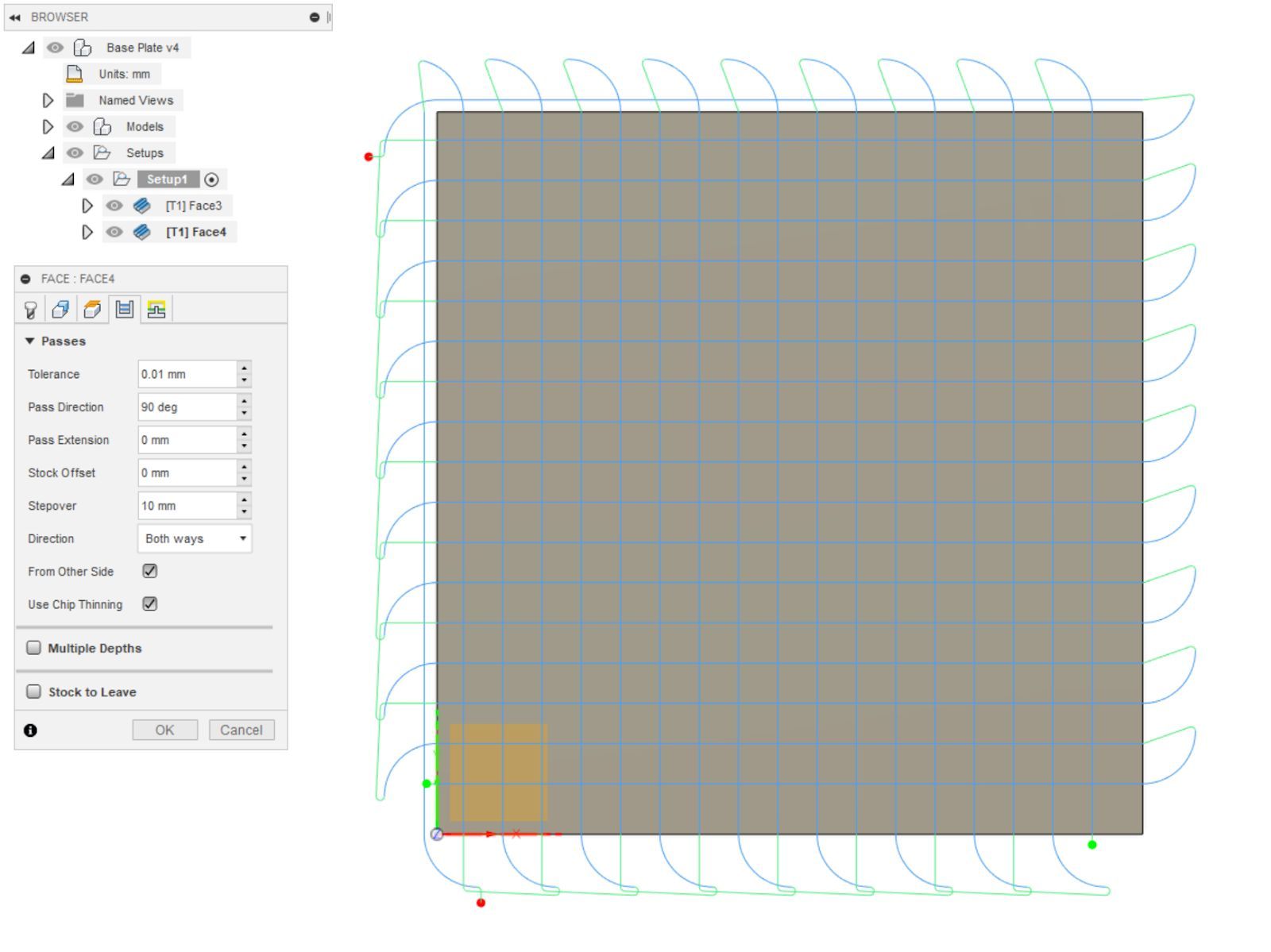
Next, I created 2 toolpaths using the face tool with one of them 90 degrees offset. The stepover is the distance between each pass and I set mine to 1cm. The drill bit I was using is 2.54cm so there was plenty of overlap between passes.
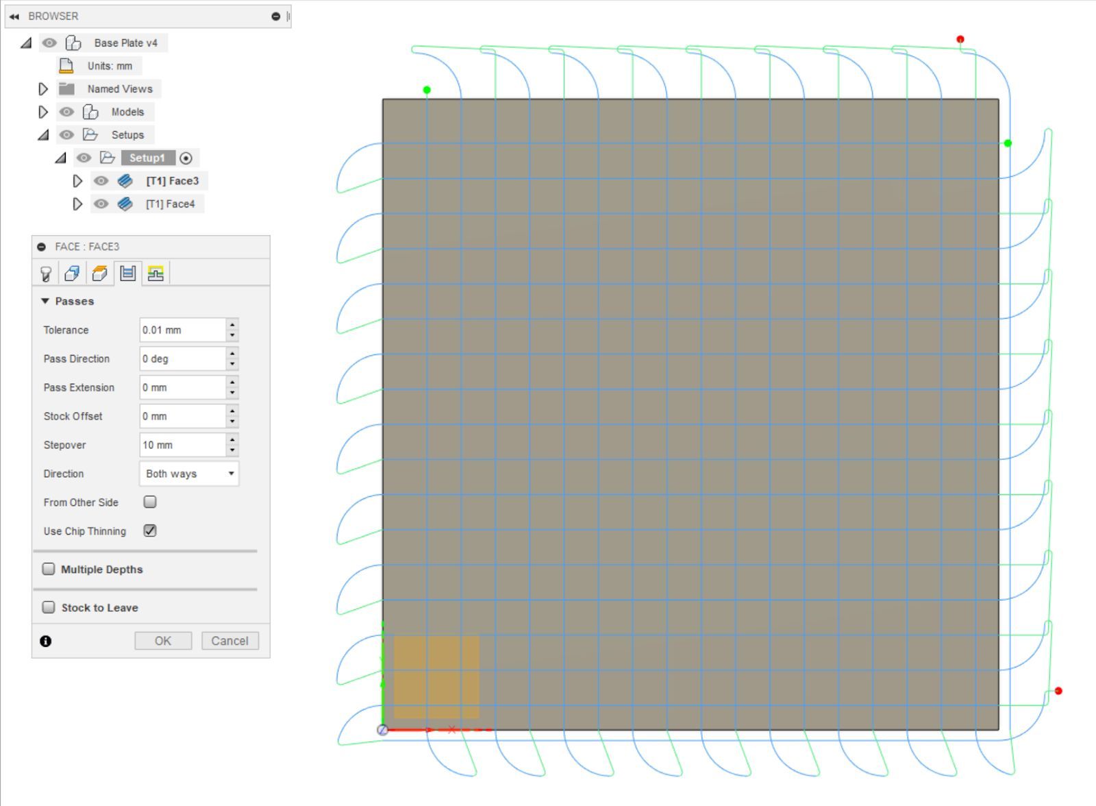
You can also choose to invert the toolpath by checking the “From Other Side” box to allow both sides to be evenly cut. Or you could just put all 4 toolpaths in 1 job, something which I didn’t think of till right now.
Step 3: Flatten the surface
Install the flattening bit. In theory you could use any flat head bit, like a 3.175mm one. It’ll take forever to flatten the whole board, and I imagine the bit would snap before you’re done.

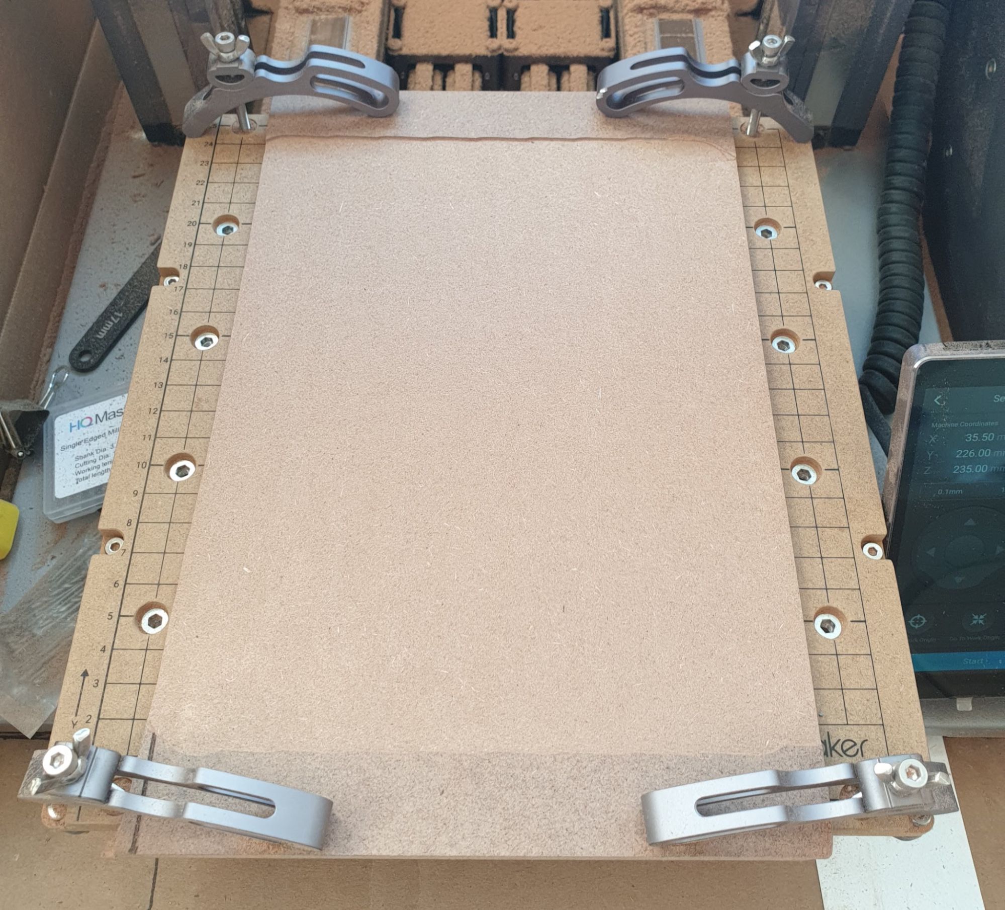
Make sure you run your boundaries and they don’t hit the clamps. I almost destroyed a clamp while running the boundaries. Then run the job.
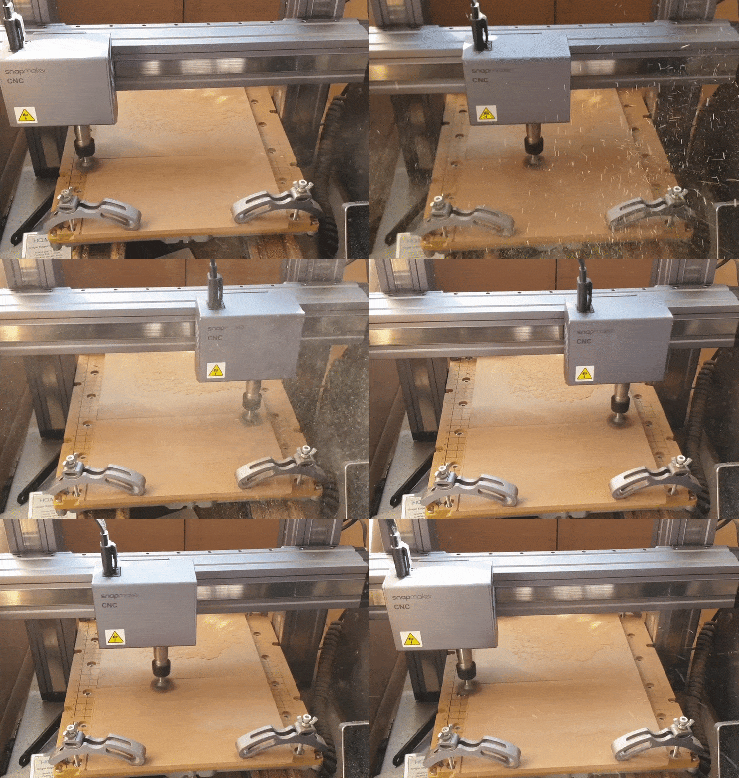
I ran this a few times, each time lowering the work origin by 0.2mm until I was satisfied with the depth of the cut.
Step 4: Create the toolpath to drill the holes
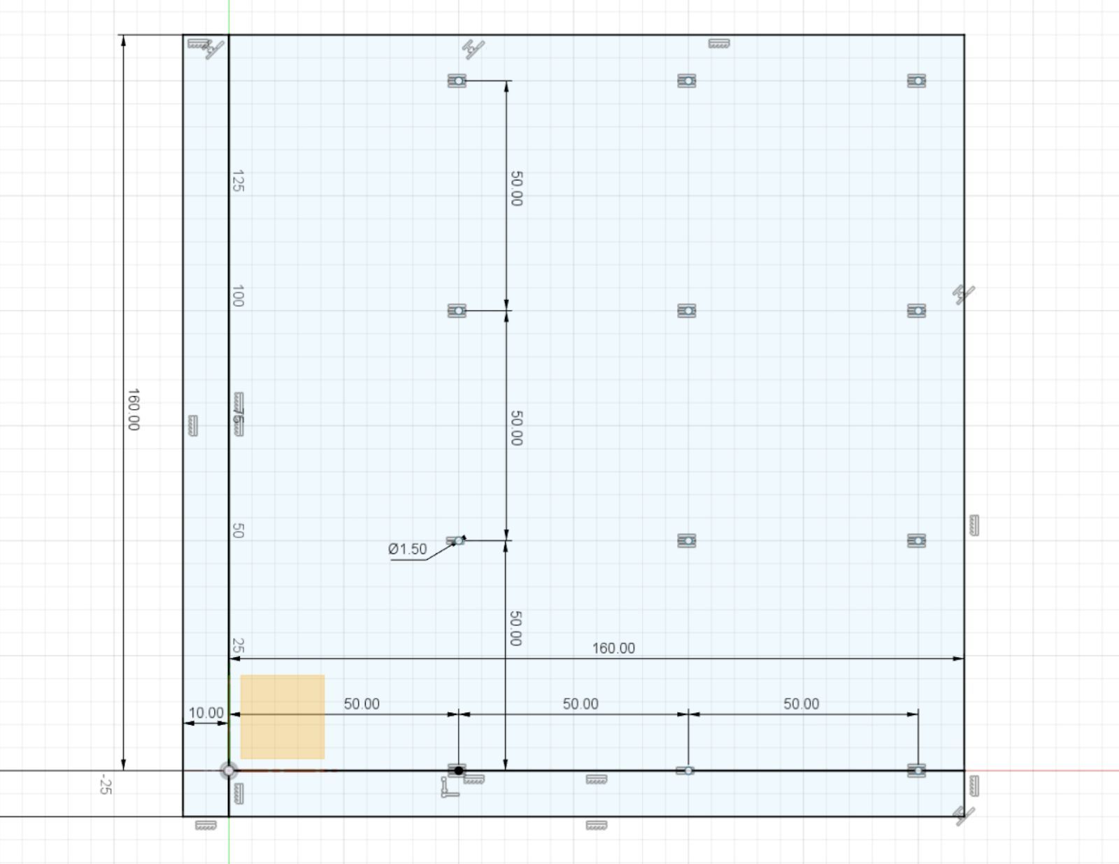
In my case I decided to create a test tool path first so I don’t destroy the board I just spent so much time flattening. I set the origin to the bottom left hole and spaced holes every 5cm apart to match the holes on the original wasteboard.
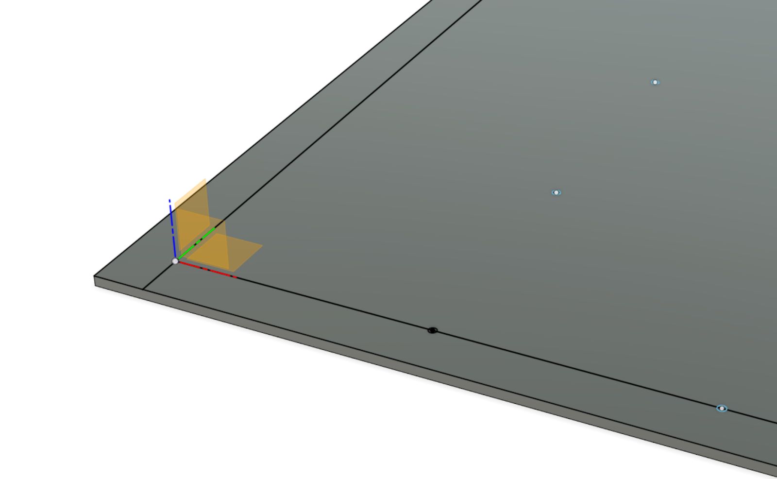
In order to align the job, I put the tool down the bottom left hole, and tried to make it as close to the center as possible. Then I set the X and Y work origins. After that I moved it back to the top of the MDF surface and set the Z origin. (You can set the origins individually by swiping to the right of the toolbar on the machine)

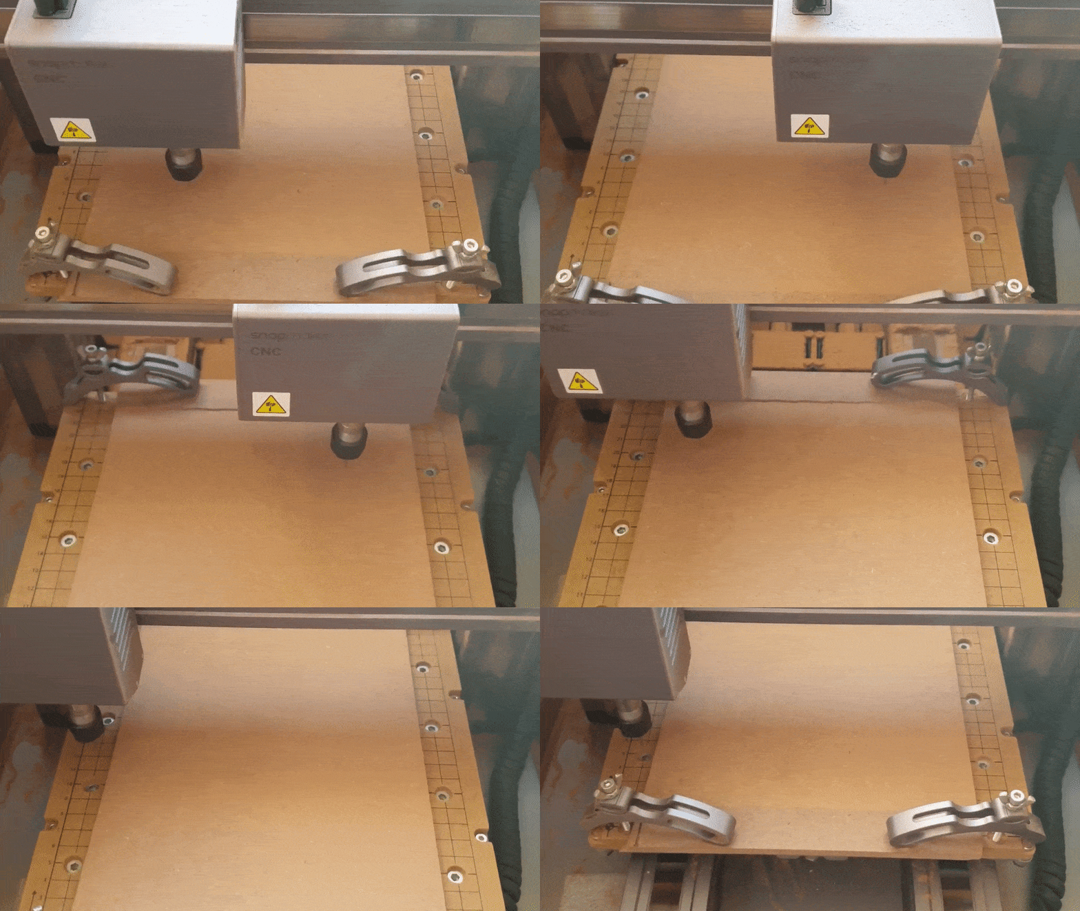

The next step was to create the job to drill the holes. I measured the hole diameter on the wasteboard, and it was 9mm. I set my hole diameter to be 7mm which is more than enough for the 4mm screws to fit in.


Step 5: Cut off the top and bottom
As the title says, I got a saw and took off the top and bottom of the board so I was left with the flattened part. Using the board is just a matter of aligning it with the holes. As luck would have it, I realised that if you put some of the spare M4x10 screws into the holes, you can get the jig aligned pretty perfectly.
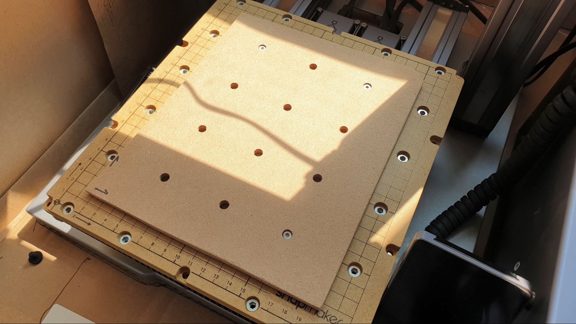
In the end, I still put a sacrificial board between the new jig I built, and the material I was cutting. I’ve invested too much into the board to bear to damage it in any way.

Notice that because I am using another piece of MDF between the jig and the actual material I'm cutting, I'm able to cut things that are bigger than the jig itself.
And that's all.
In conclusion, while this is an easy fix, it still took me a day of trial and error and I am somewhat disappointed that I still had to do this despite paying so much for the Snapmaker.